|
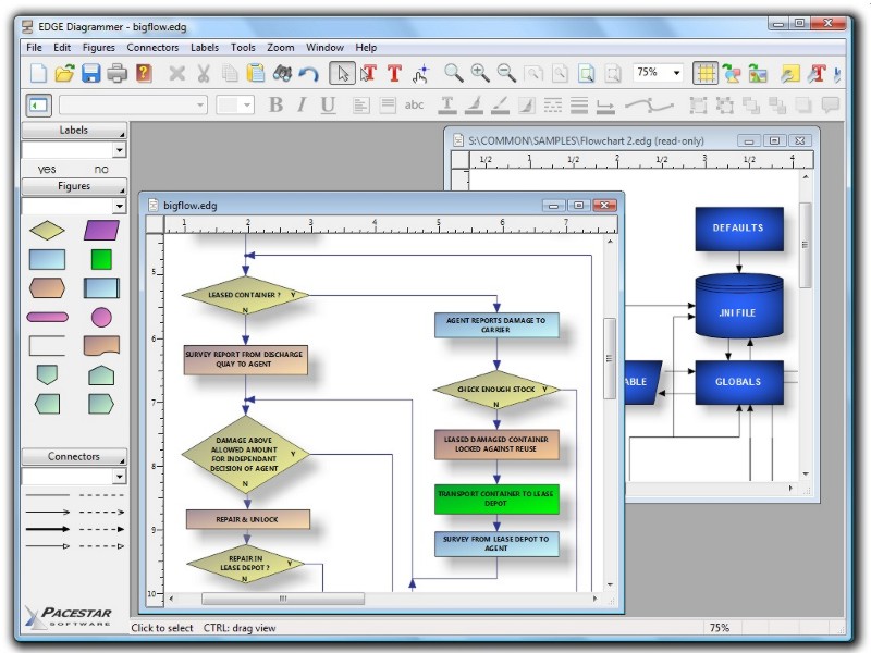
Product Description
EDGE Diagrammer is our ultimate diagramming tool. EDGE lets
you define "styles" using hundreds of predefined
drag-and-drop shapes and arrowheads. Save your styles in diagram
templates to establish your own diagramming methods. EDGE
Diagrammer comes with complete flowcharting templates, network
diagramming templates, block diagrams, org charts, and more to
get you started.
EDGE Diagrammer can create flowcharts and similar diagrams with
minimal effort. As you
draw your diagram, EDGE Diagrammer connects lines to figures and
attaches labels to lines. It remembers these relationships and
adjusts automatically when you move objects around. It can also
adjust the size of a shape when you add text to it.
EDGE Diagrammer stands out from the crowd because it can be used
effectively in the first few minutes with no prior knowledge
or training. It lets you create diagrams the way you think is
most natural. Most tasks can be accomplished in multiple ways so
that the way you prefer is usually available and does what
you expect. This attention to your convenience and productivity
is reflected throughout the product.
The diagram model is very simple. Add the diagram elements you
want, connect them with lines or arrows, add descriptive text.
The program does the rest by keeping lines attached properly,
and managing associations between shapes, lines, and text.
|
Designed for convenience...
The program's workspace is especially designed for your
ease, comfort, productivity, and enjoyment. Simple but
powerful toolbars and menus keep the most frequent tasks
handy. Objects most common to a specific type of diagram
are available with one click from the style bar on the
left of the screen. And the screen itself shows you just
what you need, exactly as it will print.
|
 |
|
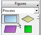
Simply drag diagram elements from the style bar and drop
them into your diagram.
|
|
Edit text directly on the screen with the text tool. What
you see is what you get. No need to open cumbersome dialog
boxes or guess how the result will look.
|
|
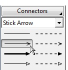
Add a connector by choosing a line style and then clicking
on the start and end objects.
|
|
Focused on simplicity...
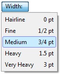
To simplify selection of sizes, use our drop menus of
pre-defined standard sizes. To select a
border width for a figure, you can choose "fine" or "heavy"
rather than figuring out the exact point size that will look
attractive both on the screen and when printed.
Of course you can select any size directly if you prefer.
|
|
- Includes hundreds of pre-defined shapes and symbols
organized in the Figure Symbol Gallery.
(more)
- Includes several pre-defined diagram templates such as
flowcharts, block diagrams, org charts, computer diagrams,
network diagrams, and general purpose diagrams.
- Create your own styles combining the attributes, shapes,
colors, and behaviors of your own figures.
- Create custom diagram templates to represent your own
diagramming methodologies and to store your custom symbol
libraries.
- Full zoom and scrolling capability with dozens of intuitive
and convenient features for easy navigation around even the most
complex diagrams.
- Connectors can have many different lines styles,
colors, curves, patterns, end symbols (arrows), and designs.
Plus you can select flow symbols that are drawn along
the path of the line.
(more)
- Connectors can have many possible terminators
(arrowheads). Many are included in the End Symbol Gallery.
(more)
- Snap grid for precise placement. The snap grid can be
visible or invisible, enabled or disabled, or customized to
different sizes for any diagram.
- Create large multi-page wall posters. Pages can be
managed separately or cropped and attached to create a poster.
- Alignment and arrangement tools. In addition to the usual
aligning, centering, and spacing features, the program also
performs subtle behind-the-scenes steps to help you keep your
diagram organized and looking good.
- Copy or export diagrams to other programs such as Microsoft
Word with OLE. Simply copy and paste into most any other
software, or link and embed into any OLE-enabled program for
full control. Export formats include WMF, EMF, BMP, and JPG.
- Import external graphics and clip-art to use in your diagrams.
Supports EMF, WMF, BMP, and JPG files.
- Hyperlinks let you link symbols to other diagrams, web
pages, or documents. Simply link any figure to another diagram
and open that diagram by double-clicking on the figure.
You can also link a figure to a web page, a spreadsheet, a
database file, or any other document.
(more)
- Create web pages from your diagrams in a single step.
Hyper-linked diagrams translate instantly to image-mapped
hierarchically-linked HTML web pages exactly as you would
expect.
|
- Auto-save and Auto-backup. Choose to save backup versions
whenever you save a file, or have a backup file saved
periodically. Fully programmable.
- Attach / detach figures in "flows". Drop a symbol
onto a line and the symbol merges into the flow automatically.
(more)
- New diagram wizard lets you select sizes, color schemes,
and initial fonts with great convenience.
(more)
- Enable "jogs" (also called jumps or crossovers) to
clarify line routing.
(more)
- Add freeform text labels anywhere on your diagram or add
specialty labels described below. You can control text
justification, color,
point size, font, bold, italic, underline, subscript,
superscript, and so on.
- Connector labels attach to a line and adjust
when the line moves.
(more)
- Flow labels attach to the point where a line meets a
symbol and adjust automatically when either the symbol or the
line moves.
(more)
- Figure labels attach to a symbol and move when the
symbol moves.
(more)
- Branch labels such as 'yes' and 'no' in flowcharts can be
snapped into place in a single step and remain attached to their
respective symbol/line.
(more)
- Line spacing is programmable. Select from many line spacing
options.
- Reshapeable figures. Many symbols contain reshape
handles that allow you to alter their shape and compartment
sizes.
(more)
- Supports 'divided' symbols with multiple
compartments for text.
(more)
- Connect to any point on a symbol on demand or by
defining fully programmable connection points.
(more)
- Group objects to create larger objects. Features
include Group, Ungroup, Ungroup All, and Regroup.
- Container symbols show divisions of larger
diagrams by creating a "box around" a number of other symbols.
The container also lets you work with the included symbols
as a unit.
(more)
- English (inches) or metric (millimeters) measurement units
- Any figure or label can include text memos which show in text balloons
- Full install/uninstall. Does not modify your operating
system files!
- Comprehensive online help.
|
|
Figures are the elements that make up a diagram. They are
also called shapes or symbols. All diagram elements are figures,
except for connectors which are lines, and labels which are text.
|
|
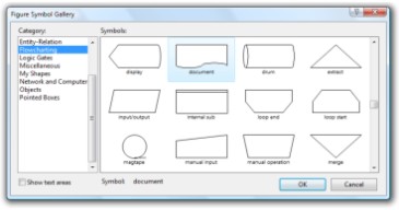
Figure symbols are the shapes that define what a figure
looks like. The figure symbol gallery contains hundreds of
different shapes sorted by functional category. You can add
any symbol to a diagram directly from the gallery, or you can
use a pre-defined figure style from a template (shown on
the left side of the workspace).
|
|
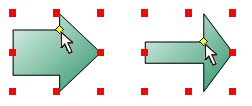
Reshape: Many predefined figures are reshapeable.
Each has one or more reshape handles (shown here in
yellow). You can adjust the reshape handle to alter the shape
of figure to your exact requirements.
|
|
Connection Points: Lines can connect to a symbol
at the center, at a connection point, or at any
point you choose. You can control the location of connection
points (shown in orange) with the connection point tool. Or
for greater convenience, just hold down the SHIFT key while
creating a connector and it will terminate where you click.
|
|

|
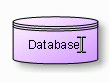
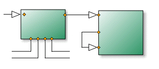
Divided symbols contain more than one text
compartment like the one shown. You can
reshape and resize each of the compartments using reshape
handles described above. Divided figures are also special
because they understand how the figure is intended to be used
and they use this knowledge to control resizing the figure
and adjusting text.
|
|
Connectors (lines) connect symbols within your diagram.
You can control all aspects of a line style including color,
thickness, line pattern, curvature, terminator symbols, and
flow symbols.
|
|
Choose from several curvature options:
Straight connectors consist of straight lines connecting
each vertex.
Rounded connectors are straight connectors with the corners
rounded off for a smooth appearance. You can control just how round
they look.
Curved connectors can follow any smooth curved path you care to
define. Curved connectors are defined by placing intuitive control points
along the path rather than the more confusing bezier points that other
programs use.
Smoothed connectors are a lot like curved connectors except they
pass right through each control point for the simplest possible control.
|
|
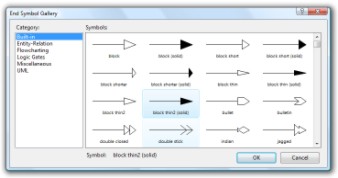
Choose from many shapes of terminators such as arrowheads and
special connector end symbols. The most common
arrow styles are built in for easy access. However, the End
Symbol Gallery stores an even wider selection organized by
category and common diagramming methodologies.
|
|
|
Patterned lines can be defined with any of twenty-four
different line patterns (or styles). With more patterns, you can
use different connector styles to represent different relationships
and easily distinguish between them.
There is no restriction to the thickness of patterned connectors.
Line patterns and line widths can be combined
however you like.
|
|
Flow symbols allow you to create
connectors whose path is defined by a repeating pattern of symbols
rather than a simple line. Flow symbols are a good way to illustrate
special relationships and sequences of events. You can control the
shapes, the colors, the size and the spacing of the symbols. Many
built-in symbol shapes are included.
|
|
|
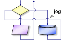
Jogs can help you clarify a connector's routing and
interaction with other lines.
When any two connectors overlap but do not connect, a jog (also
called a crossover) is drawn to clearly indicate
that the intersection is not intended as a junction. You can
control whether jogs are used for any particular diagram, and
how large they will be.
|
|
You can place text labels anywhere on your diagram. You can add
simple text labels for descriptions, titles, and notes. Plus you
can add several types of specialty labels that stick to
other objects in your diagram and reposition automatically if
needed.
|
|
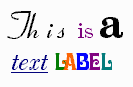
Label text can contain any combination of fonts, size, color,
bold, italic, underline, subscript, and superscript.
|
|
|
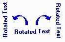
Labels can be rotated 90 degrees toward either side for
vertical labeling.
|
|
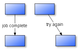
A connector label is a special kind of label that is
attached to a connector line. The label appears as standard
horizontal text within a break in the line as show. When the
line moves, the label repositions itself to remain attached
to the same point on the line. Connector labels are useful for
identifying connectors when representing branch conditions,
flows, and transitions.
|
|
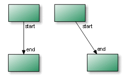
A flow label is a special kind of label that is
attached to the end of connector where it meets a figure.
The flow label automatically repositions itself if either the
connector or the attached figure moves. One of the most common
uses for flow labels is for adding "yes"/"no" labels in
flowcharts. However, labels of this type are very common in
all sorts of diagrams.
|
|
|
A figure label is a special kind of label that is
attached to any figure. When the figure moves,
the label repositions itself to remain at the same location
in relation to the new position of the figure.
Figure labels are useful for labeling shapes when the shape
does not have internal text, or when additional notes are
required. There are several powerful options
for creating, attaching, detaching, and re-positioning figure
labels.
|
|
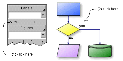
Branch labels such as the yes/no conditions in a
standard flowchart and similar pre-defined labels can be
added very easily. As shown here, adding a yes or no label
to a flowchart decision is as simple as clicking on the label
button, then clicking the label in place. If you click on the
slot where the figure and connector meet, the label
will be inserted as a flow label as described above and
will lock in place to attach to the figure and connector.
You can create labels of your own that work like this as well.
|
|
|
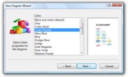
The New Diagram Wizard makes it easy to select from a
range of color schemes and diagram sizes in a single step
without the need to create a custom diagram template. It also
provides a simple mechanism to change a diagram's font
and text size throughout the entire diagram. Use of the wizard
is optional and not all diagram templates support color schemes
and preset sizes.
|
|
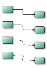
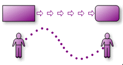
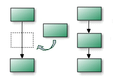
Attach and detach from flows: Easily add and detach
figures to and from a "flow". A flow is a sequence of steps
in which arrows connect one figure to another. Simply drag a
figure ("Process B" here) over the flow connector and drop it
into the flow. New connectors will form to accommodate the
figure. You can later detach the figure either explicitly
or by simply deleting it, and the flow will return to the way
it was.
|
|
|
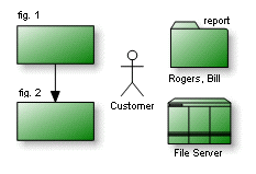
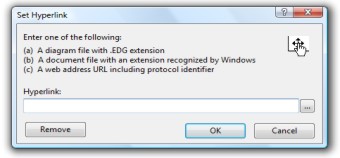
Hyperlinks let you link any object in your diagram to
another diagram, web page or document. Simply double-click on
a linked figure in your diagram to open the link.
With hyperlinks, you can represent a process as a simple box in one
diagram and link that box to a more detailed diagram that
represents the internal workings of the process. In this way,
you can construct hierarchies of diagrams showing different
levels of detail. You can also define figures as buttons to
navigate among diagrams within a project.
|
|
By linking a figure to a web page, clicking on the figure will
open up your web browser and display the web page using the
address contained in the link.
By linking a figure to a document, clicking on the figure will
open the application that can view the document such as a
spreadsheet or database.
Hyperlinks are recognized when saving a document as a web page.
|
|
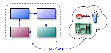
Containers are useful for showing groupings within
diagrams. A container symbol is special because it is designed
to have other symbols within its borders, yet not interfere
with editing those symbols. You can create and move objects
into the container or out of the container without special
effort. But when you move, copy, or delete a container, all
of the contained objects are moved, copied, or deleted as well.
Containers perform some of the same functions as groups, but
in a more convenient way. Using a combination of
containers and groups you can construct elaborate diagrams that
are easy to maintain and re-organize.
|
|
- Windows XP or later
- 500mb RAM
- 20 Meg free disk space
- Pentium class or better processor recommended
|